


System VI™ Switchgear
For indoor and outdoor distribution, 15 kV through 38 kV
Provides an economic and reliable alternative to traditional metal-enclosed switchgear
System VI Switchgear is available through 38 kV, 630 A continuous and load dropping, and up to 25 kA RMS symmetrical short-circuit. It includes motor-operated load-interrupter switches plus a Micro-AT® Source-Transfer Control or a 6802 Automatic Switch Control.
Transfer is achieved in about 6 seconds with a Micro-AT control or a 6802 control. Split-bus application is possible with two 6802 controls. A 6802 control can be integrated into an IntelliTeam® SG Automatic Restoration System.
The switchgear serves any number of critical loads, and it can be furnished with a variety of metering options.
System VI Switchgear offers numerous unique benefits, including:
- Compact, low-profile design. Even at 34.5 kV, System VI gear can be as little as 37 inches tall. And System VI gear has a significantly smaller footprint than conventional gear.
- Single-or three-phase protection through 600 amperes continuous with resettable vacuum fault interrupters.
- Simplified operations and enhanced safety. Routine operations can be performed quickly and easily by a single person, with no exposure to cables or energized components. Refer to Operating and Safety Benefits to see how System VI gear makes this possible.
- Microprocessor-based overcurrent control provides advanced, flexible protection. External-trip option allows fault interrupters to be tripped from transformer secondary or sudden-pressure relays.
- Source-transfer and remote supervisory automation schemes available.
- It’s affordable. Even with all its added features, System VI gear is competitive with — or offers significant savings over — conventional gear.
(On mobile, swipe left for remaining ratings information.)
| kV | Amperes, RMS | ||||||
|---|---|---|---|---|---|---|---|
| System Class | Max | BIL | Main Bus | Load-Interrupter Switch Continuous & Load Dropping | Fault Interrupter | Short-Circuit (Sym.) | |
| Continuous & Load Dropping | Interr. (Sym.) | ||||||
| 15.5 (12) | 15.5 (15.5) | 95 (95) | Up to 2000 (2000) |
600 (630) |
600 (630) |
Up to 25 000 (25 000) |
Up to 25 000 (25 000) |
| 27 (24) | 29 (29) | 125 (125) | |||||
| 38 (36) | 38 (38) | 150 (150) | |||||
| 15.5 (12) | 15.5 (15.5) | 95 (95) | Up to 2000 (2000) |
900 (900) |
900 (900) |
25 000 (25 000) |
25 000 (25 000) |
| 27 (24) | 29 (29) | 125 (125) | |||||
| 38 (36) | 38 (38) | 150 (150) | |||||
• Other ratings are available. Contact your local S&C Sales Office for more information.
S&C’s unique Vista Underground Distribution Switchgear is at the heart of every System VI Switchgear lineup. Vista gear provides a major advancement in operating simplicity and safety for medium-voltage switchgear.
All medium-voltage components are isolated inside the grounded steel tank. Cables are connected via insulated separable connectors (elbows). But unlike conventional elbow-connected gear, with Vista gear there’s no need for operating personnel to move, test, and ground cables during routine operations. Such procedures are awkward and time consuming, and — most importantly — personnel are not fully isolated from medium voltage once a cable is removed from its bushing.
It’s all made possible by Vista gear’s numerous innovations, including:
- Clearly visible open gap and ground positions on all switches and fault interrupters.
- Especially large viewing windows for positive confirmation of closed, open, and grounded positions.
- Operating controls isolated from medium-voltage cable terminations.
- Optional built-in voltage indication on operating side of the gear.
- Optional low-voltage phasing feature on operating side of the gear.
- Ground positions are rated for a minimum of 3 fault-closing operations at maximum rated short-circuit current. Accidentally grounding a live cable is not a potentially dangerous situation, as it can be when physically handling live cables and elbows.
System VI Switchgear can be custom-designed to meet a wide variety of requirements.
Each Vista UDS unit can include any combination of up to six load-interrupter switches, fault interrupters, bus taps, or bus-tie switches. Multiple Vista units can be connected via air-insulated transition bays. Metering bays and other metal-enclosed switchgear components can also be incorporated in the lineup, to provide an unlimited variety of configurations.
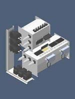
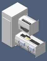
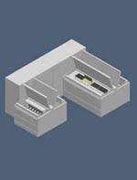
In addition, the physical arrangement of Vista units and bays can be customized to meet specific requirements. A few examples are shown here.
Incoming section is attached to a frame above the outgoing section. (The enclosure of the metering bay has been removed to show the bus terminations.)
Incoming and outgoing sections are stacked, connected through the metering bay.
Incoming and outgoing sections can be attached to the metering bay in a U-shaped configuration to fit the available space.
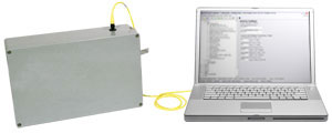
Time-current characteristic curves are easily set with a user-supplied personal computer.
A unique microprocessor-based overcurrent control provides fault detection, and initiates operation of the resettable vacuum fault interrupters. This full-featured control offers exceptional flexibility and reliability, and includes features unavailable in other manufacturers’ devices — or available only at substantial cost.
Using virtually any personal computer, and with no special software, the overcurrent control can be readily programmed in the shop or in the field.
- Four families of curves. Standard “E” and “K” speed curves plus special, customizable “coordinating-speed” tap and main curves.
- Superior coordination with upstream protective devices and downstream power fuses. Minimum total clearing time, from initiation of a fault to total clearing, is 40 milliseconds (2.5 cycles). Coordinating-speed curves were specifically created for optimal coordination on underground distribution systems.
- Custom curve attributes. Coordinating-speed curves can be easily modified to include instantaneous pickup levels and definite time delays.
- Separate phase and ground curves are standard — allowing better coordination with source-side breaker trip settings.
- No extra “wake-up” time. If closed into a fault, System VI Switchgear will trip and clear the fault per the selected TCC, with no additional delay.
- Self-powered. Current transformers on fault-interrupter ways provide sensing and power.
- Event recorder captures information on the last twelve operations of each fault interrupter.
- Optional external trip provisions offer additional functionality. Input from external sources such as transformer sudden-pressure relays can also trip the fault interrupters.


